Inventronics Quick Select
A compact route from project conditions to a reviewable luminaire shortlist.
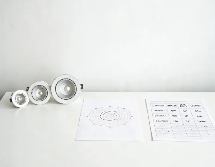
Four filters, one usable handoff
Start with calculated requirements rather than a nominal wattage. Confirm maintained light levels under actual room geometry and reflectance.
Choose recessed, surface, suspended, track or wall integration. Ceiling void, cutout, access and visual alignment can remove unsuitable families early.
Use IP and IK only for the conditions they address. Cleaning chemistry, ambient temperature and corrosion exposure require separate confirmation.
Match DALI-2, 0–10V or switching to the controls architecture and define who commissions groups, scenes and sensors.
Carry these values into review
| Light | lm, beam angle, UGR, CCT, CRI |
|---|---|
| Electrical | Power factor, THD, driver and dimming interface |
| Environment | IP, IK, ambient temperature and service access |
| Evidence | IES/LDT, LM-79 context and applicable UL/CE documentation |
Higher lm/W can reduce connected load, but it may not preserve visual comfort or color quality. Integrated components can reduce size, while replaceable drivers may simplify future service. The shortlist records these trade-offs instead of hiding them.
Values remain configuration dependent. Final photometry, compliance, availability and lifetime evidence must be checked for the selected model and market version.
Driver-specific checks after the first filter
Luminous flux is an application target, not a direct driver setting. The luminaire design translates that target into LED module voltage, current and power. Enter the full forward-voltage range at operating temperature, the desired programmed current and any power ceiling before comparing driver windows. A match at nominal conditions can fall outside the window when the module is cold or hot.
Mounting describes more than a bracket. Decide whether the power supply sits inside a luminaire, in a remote enclosure or above an accessible ceiling. Record ambient limits, thermal case measurement point, conductor length and service clearance. IP and IK ratings address specific ingress and impact tests; they do not establish corrosion resistance, chemical compatibility or suitability for every orientation.
The control filter should capture interface and behavior. For 0–10V, document sourcing or sinking expectations, minimum dim level and off method. For DALI-2, identify addressing, groups, scenes and commissioning ownership. Where no control system is required, confirm whether fixed-output operation or simple switching changes emergency and energy-code coordination.
Use the result as a handoff, not an automatic approval. Compare input voltage, power factor, total harmonic distortion, inrush, surge strategy, output ripple and thermal derating in the current model documentation. UL, CE or RoHS evidence is checked for the destination and exact version. A bench sample can verify start-up and dimming with the intended load, but it cannot reproduce every field temperature or long-term surge event.
Have a shortlist reviewed.
Send the application, plans and selected filters to an application specialist.